
Take your Raspberry Pi into the wild with the Mantis robot kit. In this series of articles, I’ll discuss the process of building, powering, connecting, and controlling your own Mantis robot, and I’ll also point out some potential pitfalls.
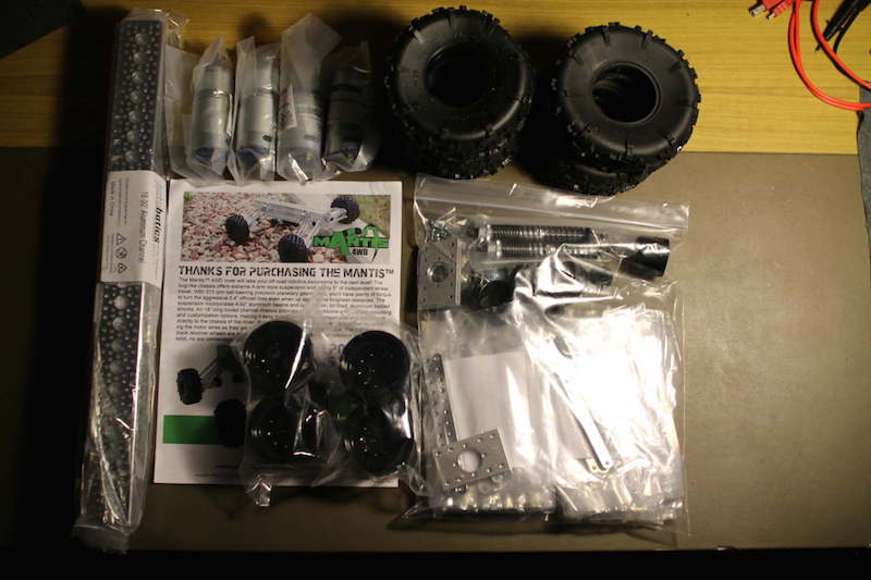
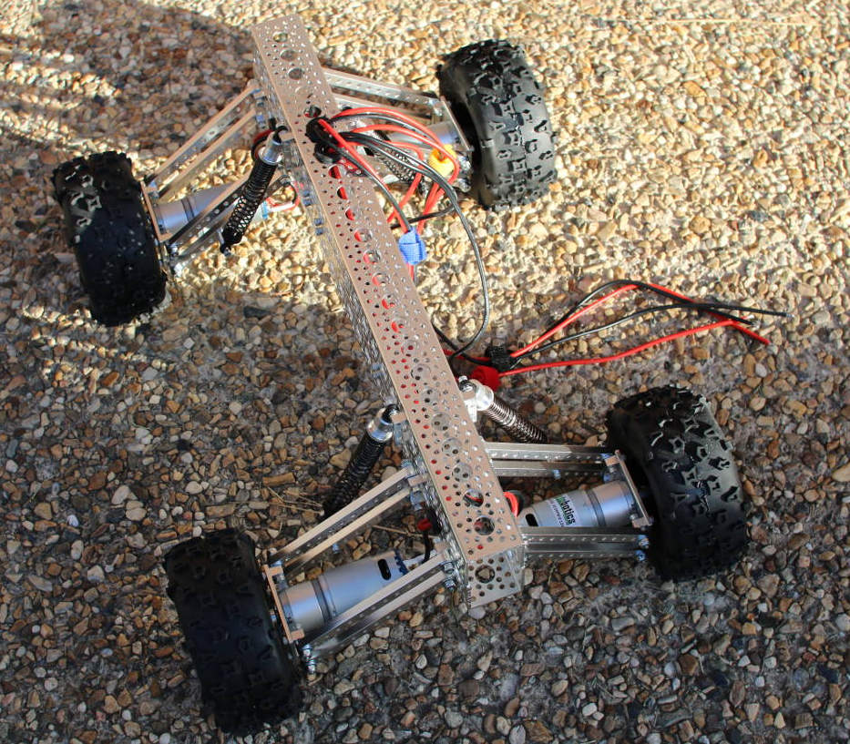
The Mantis is available in four– and six-wheel configurations and includes an electric motor to drive each wheel with potentially a little over 2 foot-pounds of torque. Generating such torque allows the Mantis to run over uneven terrain, such as loose rocks, small logs, and other obstacles, and climb some reasonable hills.
Although there are general purpose headers on the Raspberry Pi to allow you to communicate with other hardware, you can’t run large electric motors directly from those headers. Motors want higher voltages than the Raspberry Pi can directly supply and will draw far more current than the Raspberry Pi can directly provide.
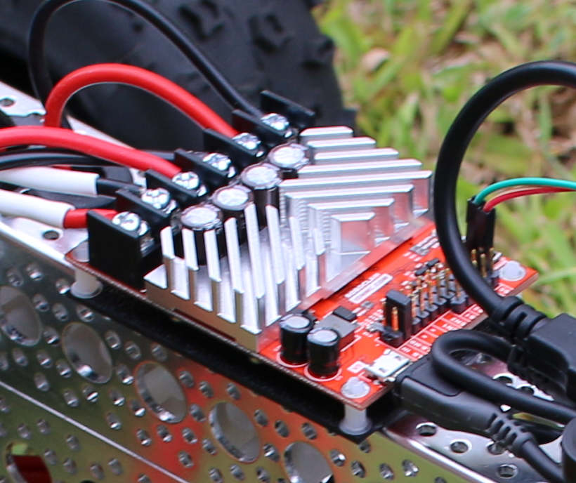
As mentioned in a previous article, you will want to use a motor controller chip or board to interface with electric motors. The motors on the Mantis are rated to draw up to 20 amps of power each. So, I will use a RoboClaw motor controller board that is rated to deliver up to 45 amps per channel in this article (Figure 3).
To run a Linux machine on a robot, you probably want to obtain a stable power supply from a battery, and will likely want to talk to your Raspberry Pi through a WiFi adapter. Other input and output, such as how to control the speed and direction of the robot and being able to see how much battery power remains, call for some form of wireless connection.
The RoboClaw includes a Battery Eliminator Circuit (BEC) that lets you to run the entire robot from a single battery. A large battery that can handle the current draw of the motors is attached to the RoboClaw. This single battery will usually be a two- or three-cell LiPo battery that will run at 7.4 or 11.1 volts. The actual voltage from the battery will change over time as you draw power from the battery, and it discharges. The BEC on the 45A RoboClaw controller offers up to 3 amps at a stable 5 volts which is fine to run the Raspberry Pi.
The only difficulty here is that the BEC on the RoboClaw uses dupont headers, much like the connecting cables on breadboards, while the Raspberry Pi wants to draw its power from a microUSB cable. I opted to create my own custom cable by wiring the positive and negative pins of a microUSB cable to half of a breadboard cable.
For each motor on the Mantis to generate its maximum torque, it might want to use 20 amps of current. You should have a battery that can deliver at least 80 or 120 amps of current depending whether you have the four- or six-wheel Mantis. If you are running the motors on 10 volts, then you might potentially draw over 1 kilowatt of power. It is good to know the worst case power draw for the motors on a robot so you can work out the battery requirements, and what cabling you want to use to connect to the motors so that the system does not burn up cables or suffer a catastrophic battery failure. The latter can occur if you try to draw more current from a battery than it is rated to deliver. High power batteries can also fail if they have been charged incorrectly or physically damaged. Be sure to familiarize yourself with the procedures for safely using your batteries.
Building the Mantis
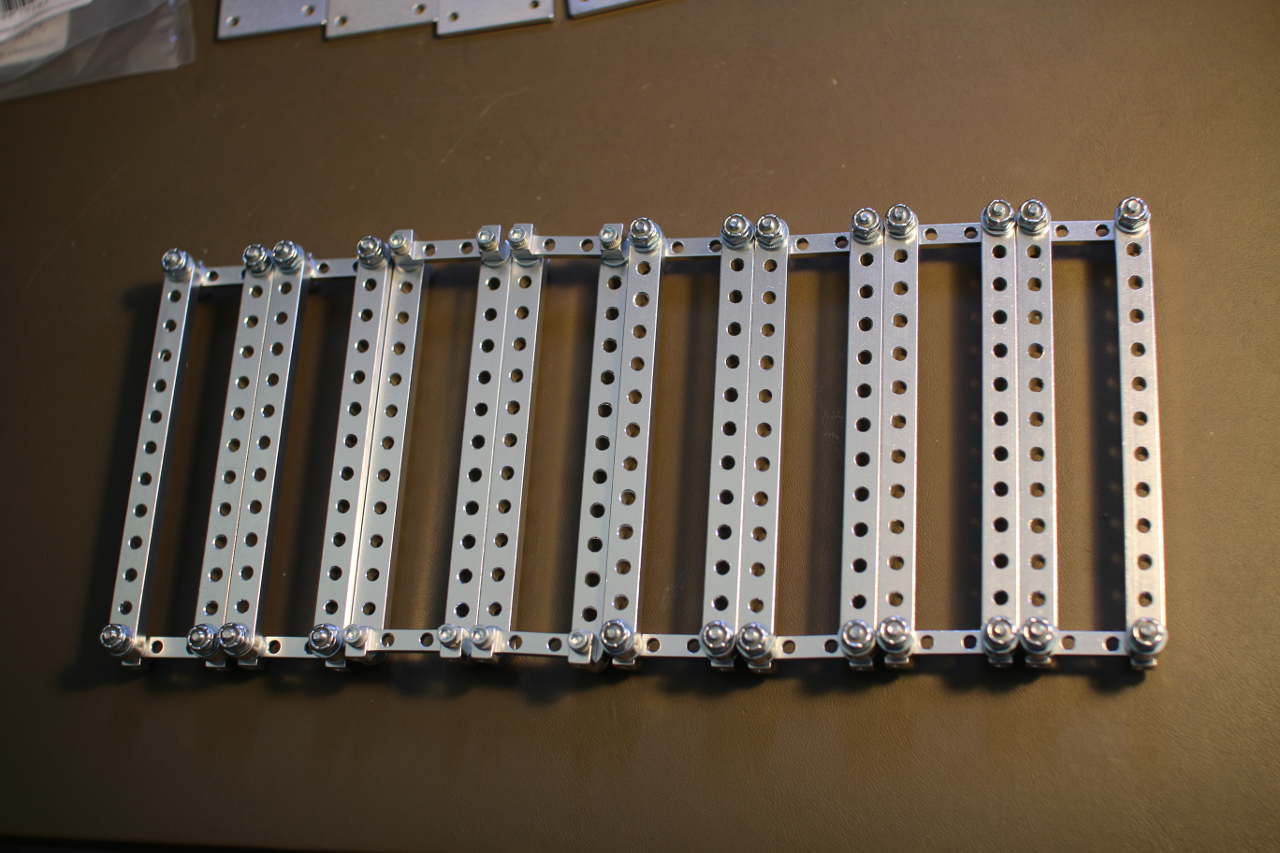
ServoCity has an assembly video on YouTube showing how to put the Mantis kit together. I soldered silicon-coated wire to the motors before mounting them to the Mantis and routed the wires through to the top of the Mantis before securing the top channel to the bottom channel. Each motor mount has four beams that attach back to the main channel. Two of each of these beams have a “90 Degree Dual Side Mount D” at each end of it. Given the number items to connect, having a ratchet that can handle the 6-32 locknuts will make these all go together much more quickly.
Next Time
In the next article, I’ll show how to attach the motors, connect the RoboClaw to your Raspberry Pi through a USB port, and supply the RoboClaw with its own power source to talk to the Pi over USB.
Read Part 2 here.


